How to charge a LiFePO4 battery with a USB charger
Thu Feb 29
Written by: Casey O.
In my quest to get the cheapest backup energy storage for small electronics, I built a site that lists LiFePO4 batteries by their price per kWh. By capacity or price per kWh, LiFePO4 batteries like these are much, much cheaper than big USB power banks. My use case is a backup battery system that does not need to be very portable, for charging phones and other small electronics if the power goes out for a few days.
The problem with buying straight batteries is that you still need to get energy in and out of the battery in a useful way. I think the cheapest way to do both, assuming you have a USB-C cable and USB-C power brick laying round, is with a “IP2368 module”,a PCB with bidirectional USB-C charging that can be configured for LiFePO4 batteries.
Here’s what you’ll need to get started:
- A 12V LiFePO4 battery
- IP2368 Bidirectional USB-C Charging Module
- USB-C wall charger
- USB-C cable (nice to have one with a wattage display)
- Soldering iron
- A few short wires and connectors for your battery
The IP2368 modules cost around $15 and require just a little basic soldering to configure.
Let’s set one up!
TL;DR: Put a glob a solder on the pads labelled R2 and solder a few wires to the BT+ and BT- pads.
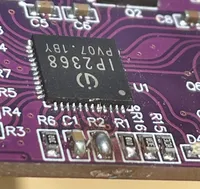
Documentation is just okay. Let’s start with the datasheet. These chips can be configured for a few chemistries and voltages and capacities. In our case, we’re not designing a PCB, but buying premade modules with resistors already chosen for us. Every one of these boards I’ve seen is configured for a 4S battery, meaning four cells in series. In our case, a 12V LiFePO4 battery. You can check the product description or the resistor values if you’re not sure.
The first thing we need to do is short the BATT_MODE pin, which on our PCB is labelled R2.
There are other configuration options, but I don’t bother. You can change other resistors to let the chip know the capacity of your battery. I believe this is only used to calculate charge level, displayed by a few LEDs, and that’s not important to me. Also, if you have a battery with cells in some other configuration, you can also configure it for that. Desoldering and soldering surface mount components is a faff, so I don’t bother.
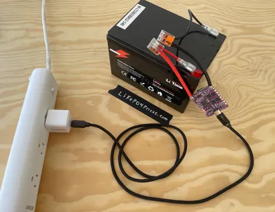
Next, we solder a few wires to the BT+ and BT- pads, and connect it to the battery. I’ve used some Wago connectors to make my life a little easier, and a few pieces of wire with connectors I had lying around.
The USB-C port is bidirectional, so you can also use it to charge your phone or other small electronic devices.
Quirks
These modules are advertised as 100W chargers, I don’t feel the need to push them anywhere near that far. My use case is to have ~150Wh of storage so my family can charge their phones and maybe some flashlights if the power goes out for a few days. I keep it topped up for that contingency. I have a 12V 12Ah battery, and I generally charge it with a 30W USB-C charger, so it can take 5+ hours to charge, which is slow, but charging slowly is healthier for the battery. This module isn’t a silver bullet, if you have a much larger battery that you want to charge from the wall very quickly, there are different (and more expensive) solutions.
One final note, a quirk of these modules is that they need to ‘start’ by being connected to a source of power. If you install it and directly try to charge your phone, the module will not do anything. Connect it to the wall, it will ‘wake up’, and then you can disconnect the wall charger and charge your phone from the LiFePO4 battery. If you leave the module attached, not such a big deal, but if you plan to remove it from the battery, you’ll need to ‘jump start’ it with a wall charger or another USB power bank when reconnecting.
This post may contain affiliate links, which means if you make a purchase I may recieve a a comission. As an Amazon Associate I earn from qualifying purchases.